We found that many people have made their own KMG clone and decided to take on the challenge. At first, we were going to design a grinder from scratch using pictures, but a little Googling started to uncover prints that were already posted online. I finally stumbled onto a website http://sayberosg.com/ in which the owner built a KMG clone grinder, but mounted the frame onto a pivoting base so that the whole grinder could be tilted 90*. The whole premise of the Sayber OSG website is for people to download his prints, use them to make the grinder and then to share any improvements with the group.
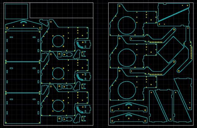
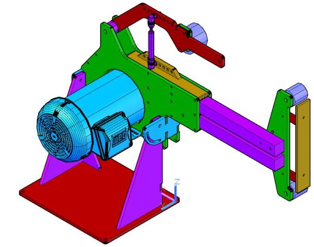
I downloaded the prints and converted the DXFs into a 3D model in AutoCAD so a friend and I could make any modifications. After going back and forth a few times we settled on the final model below. At first glance it looks pretty much like the Sayber OSG but there are some minor differences.
 1) The Sayber OSG was originally designed so that a person could download the prints, take them to a local waterjet or laser cutter, and them bring the parts home and assemble with basic tools (drill press, angle grinder, drill/taps). I really didn't want to drill and tap dozens of holes when I could easily weld the grinder together so I converted the prints for welding. Besides for deleting a bunch of holes, I modified the front and rear pivot plate to allow for welding and shortened all of the tabs in the base by 1/8" so that I would have some space to weld. I may have been expecting a little too much of my plasma cutter to have these pieces fit together nicely like a puzzle, but actually it wasn't too bad. A little bit of hand filing to remove the radii in the corners of the tabs/slots and the assembly went together nicely.
2) Most people who build these grinders use a 1 or 2 hp motor. A little bit of research showed that most wished that they had gone with 3HP. We made a few changes to the motor pass-through and raised the pivot point up 2" to account for the extended length of a 3HP motor. You can never have too much power!
3) The original Sayber OSG design uses springs to keep the belt under tension. I converted the tracking arm to use a gas shock for tension. I moved the pivot point up and back to make some extra room for the shock and placed a row of holes on the arm and on the frame. This allows the shock to move forward and backward so that different tensions could be applied for different types of sanding belts. In the picture below, I show the bottom mount being separate pieces like the Sayber, but I changed it in the final design so that the spacer is machined from aluminum rather than being stacked cut pieces. The shock, shock ends and ball studs are inexpensive and available from McMaster Carr.
4) There are also a lot of small changes such as widening the front and rear supports due to the extra height for the 3HP motor, changing angles / fillets to make parts match better, etc.
A friend and I cut three sets of parts last weekend and went to town on the slots/tabs with hand files to get everything pieced together nicely. Is there anything that I could do to make this puzzle piecing process easier in the future or is it just the nature of the beast when cutting small 3/8" wide slots in 3/8" thick plate. I calculated what the taper should be with a 2* bevel and increased the openings by that amount (x2) plus a little extra for good measure. I made a few test cuts and the test tab fit into the test slot, but that was with a brand new electrode and nozzle. When it got to the point of cutting the actual slots I think there must have been some change in how the electrode was cutting because it required filing to fit. I think next time I do something like this, I will put the critical cuts on a separate layer and cut them first with fresh consumables.