One)
struggling here to help you.... can you take some photos of the drives (I am at a total loss as to how you can have 64 steps difference from one side to the other side of the machine.....
can you take some screenshots of your mach4 setup screens and I'll try to help.
Two)
If you look at your Ether-Mach Config.pdf you will see that Port#1, Pin#14 is actually an OUTPUT pin.... you cannot connect your home switch for the A axis because it won't work. You need to move it to Port#1, Pin#15 as that is an INPUT pin.
Three)
your colour coding / key or legend is wrong (Orange should be OUTPUTS, and Green should be INPUTS)
Four)
Can you explain what Port2, Pin16 is please?
My (kinda) budget build 4x4 plasma table
-
robertspark
- 4.5 Star Elite Contributing Member

- Posts: 1816
- Joined: Mon Jun 12, 2017 6:43 pm
-
robertspark
- 4.5 Star Elite Contributing Member
- Posts: 1816
- Joined: Mon Jun 12, 2017 6:43 pm
Re: My (kinda) budget build 4x4 plasma table
robertspark wrote: ↑Mon Jul 06, 2020 3:50 pm Two)
If you look at your Ether-Mach Config.pdf you will see that Port#1, Pin#14 is actually an OUTPUT pin.... you cannot connect your home switch for the A axis because it won't work. You need to move it to Port#1, Pin#15 as that is an INPUT pin.
but then your wiring is correct on the markup of the C25 c25_BOB_wiring.pdf
-
robertspark
- 4.5 Star Elite Contributing Member
- Posts: 1816
- Joined: Mon Jun 12, 2017 6:43 pm
Re: My (kinda) budget build 4x4 plasma table
what belts are you using and what pulleys on the stepper motors?
Are they HTD profile or MXL?? or what??...
Pulleys, how many teeth?
Why are you using different micro steps settings for the motors? (curious if using the same belt and pulleys on all axis)??
Are they HTD profile or MXL?? or what??...
Pulleys, how many teeth?
Why are you using different micro steps settings for the motors? (curious if using the same belt and pulleys on all axis)??
-
robertspark
- 4.5 Star Elite Contributing Member
- Posts: 1816
- Joined: Mon Jun 12, 2017 6:43 pm
Re: My (kinda) budget build 4x4 plasma table
here is another one for you..... can you explain how you get LESS steps per unit when you increase the number of microsteps? Motor tuning worksheet_pdf.pdf
I did use a 20Tooth 5M HTD belt..... set on 10 micro steps....
hence I had 20T x 5mm/tooth = 100mm travel per motor revolution.
100mm / 200 motor full steps = 0.5 full step resolution.
because I was running 10 micro steps.... 0.5 full steps / 10 = 0.05mm per micro step
to convert mm / micro step to number of microsteps per mm >> 1 / 0.05mm = 20 steps per mm.
If I was working in inches..... 20 x 25.4 = 508 steps per inch.
(just recently changed to MOD 1 rack with a 20T pinion, direct driven).
[200 steps (per rev) x 10 micro steps ]/ (20T x Pi) = 31.8 steps / mm (or 808.5 steps per inch)
if the micro steps get bigger, then the steps per unit increase too.
-
Dmaxpwr
- 2 Star Member

- Posts: 57
- Joined: Sun Dec 29, 2019 4:16 pm
Re: My (kinda) budget build 4x4 plasma table
Robert,robertspark wrote: ↑Mon Jul 06, 2020 3:50 pm One)
struggling here to help you.... can you take some photos of the drives (I am at a total loss as to how you can have 64 steps difference from one side to the other side of the machine.....
can you take some screenshots of your mach4 setup screens and I'll try to help.
Two)
If you look at your Ether-Mach Config.pdf you will see that Port#1, Pin#14 is actually an OUTPUT pin.... you cannot connect your home switch for the A axis because it won't work. You need to move it to Port#1, Pin#15 as that is an INPUT pin.
Three)
your colour coding / key or legend is wrong (Orange should be OUTPUTS, and Green should be INPUTS)
Four)
Can you explain what Port2, Pin16 is please?
You are absolutely correct, I totally FUBAR'd my worksheets. I'll try to answer the the best I can;
Q 1) I'm using KL5056 stepper drivers, I attached a photo but it was taken before I set the steps. I'll take better pictures tomorrow.
Q 2/3) The worksheets are totally screwed up, I'll attach an updated version. The input wire is on Port#1 Pin#15
Q 4) That is the signal from the proximity switch that senses when the Z axis bottoms out and slides up to trigger the switch. I have it triggering the "Probe" input in Mach4.
Belts & pulleys) They are XL 1/5" pitch, 12 tooth on the X, Y & A axises. I tried figuring out the steps, but they were way off. So I just used the step wizard in Mach4 to determine the SPU.
I'm sure the less SPU as micro steps increase is a screw up of mine. As far as why I'm running the X & Y/A axis at different steps, well, I was trying to get a minimum of 300 ipm. I was able to get it on the A axis, can still only consistently get to 225 ipm. on the Y/A axis, then it starts missing steps.
When I set the steps on the Y/A axis the same, I can't get over 75 ipm. without missing step issues. So I took the gantry apart and ran the SPU wizard on the two motors independently. I got each motor to within 1/64" over a 42" span and those were the SPU that I cam up with.
Another issue that I noticed is that when I jog the Y/A axis slowly, I can see that the A axis will move slightly before the Y axis moves.
I'll get some photos and screen shots tomorrow after work and post them up .
Thanks so much for your help!!!
You currently do not have access to download this file.
To gain download access for DXF, SVG & other files Click Here
DYI 4' x 4' CNC plasma table (in process)
Sheetcam
Mach4
Miller Multimatic 200
Hypertherm 45xp plasma cutter
Sheetcam
Mach4
Miller Multimatic 200
Hypertherm 45xp plasma cutter
-
robertspark
- 4.5 Star Elite Contributing Member
- Posts: 1816
- Joined: Mon Jun 12, 2017 6:43 pm
Re: My (kinda) budget build 4x4 plasma table
ok the bump up is known as a floating head input (it will take some time to get the terminology but it can confuse the hell out of us if we are all using different names)
you have it shown on port 2 pin16, this is an output.... it needs to be on an input pin (pin 10, 11, 12, 13 or 15)
the other type of touchoff sensor is an ohmic probe input.
you have it shown on port 2 pin16, this is an output.... it needs to be on an input pin (pin 10, 11, 12, 13 or 15)
the other type of touchoff sensor is an ohmic probe input.
-
robertspark
- 4.5 Star Elite Contributing Member
- Posts: 1816
- Joined: Mon Jun 12, 2017 6:43 pm
Re: My (kinda) budget build 4x4 plasma table
I'm curious, why did you decide on using 12 tooth pulleys?
I decided to use 20 tooth on mine because:
1) they were a round number [200 /(20T * 5mm) = 2 steps per full step], so there were less likely to be rounding errors in Mach3 (what I started out with)
2) more teeth means the load would be spread across more contact spots so the belt is less likely to slip
I would suggest consider getting 3 pulleys with 20 teeth if you can. The torque being output from the stepper motor will then be spread across more contact spots on the belt, plus the machine is likely to achieve faster speeds and acceleration given the steps are bigger, the effect of jolt / jerk is less and the motors will be turning slower to achieve the higher speed than they would have had to for a motor with smaller pulleys.
(have a look at this example torque curve for a stepper motor, all stepper motors have a similar sort of profile curve [ignore clearpath steppers as they are done differently, I am talking about buying a generic stepper motor and driver here]
https://www.orientalmotor.com/images/st ... torque.jpg
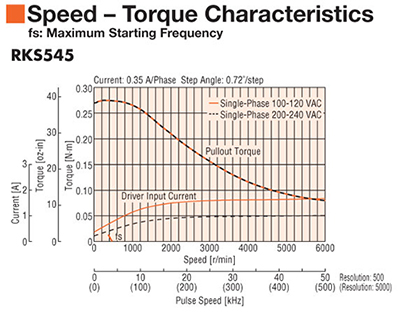
article to read: https://www.orientalmotor.com/stepper-m ... otors.html)
Using your example: Some other examples of round step numbers:
16T, 20T & 25T
depends what is available in your belt size as standard pulleys.
Here is a document someone has put together as a PDF of some guidance from the GeckoDrives website. When I started out, Gecko were one of the few sources of information so it was kind of a really great resource, now the web is full of information and misinformation.
I would suggest that you consider PDF Page 14 regarding stepper motor microsteps resolutions and accuracy.
http://yertiz.com/cnc/steppers-gecko.pdf
I have always stuck to about 10 microsteps and never gone beyond it (much)...... (OK I have gone to 256 microsteps on my 3d printer..... but that is because the stepper drives are trinamic stepper driver TMC2209 and are something new and run on very little current and run on a serial signal not step+direction.... but I digress.... ) for a general run of the mill stepper motor and drive, I'd suggest 10 microsteps is all you need really..... some stepper drives do something called "morphing" but that is rare from what I've seen (they can change from microstep outputs to full step outputs at higher speeds despite being given a microstepping trane from the microcontroller [gecko's do this])
What Voltage are you running the KL5056 stepper drivers at?
Do you have a datasheet for the stepper motors? (link / model number)?
You currently do not have access to download this file.
To gain download access for DXF, SVG & other files Click Here
-
robertspark
- 4.5 Star Elite Contributing Member
- Posts: 1816
- Joined: Mon Jun 12, 2017 6:43 pm
Re: My (kinda) budget build 4x4 plasma table
Another observation....
(sorry my drip feed of posts...)
Cable ties...... and singles! (single core wire)
Whilst I like your neat cabinet wiring (and mine is a "£$% pile! (but I have a LOT in it) .... and I was an electrician and technician and have done a fair bit of panel wiring at one point! [~20 years ago])...... bundling all your cables into neat bunches when you have high speed and low voltage low current signals alongside high current and higher voltage signals is a NO NO! It will give you no end of problems and probably why you are getting different steps as I thought you had quite big stepper motors (need to read your early posts again).
Basically I would suggest that you invest in different types of cables and separate your cables as much as is possible.
My step and direction signals are run in shielded CAT5 cable (data cable) so that they have much less chance of being affected by stray currents and inductance.
My stepper motor cables are run in 4core flexible cable (not the best.... but they are all together neat and the cable has a rubber insulating sheath so it provides distance between adjacent cables).
I suspect that you are getting signals affecting the other drive signals and that is why your steps are all over the place.
Also think about your cable routing...... if you run cables parallel to each other the magnetic flux from one cable will affect the adjacent cables where as if they run at right angles the area of magnetic flux contact will be less..... hence my drives are central (at the bottom of my cabinet) and their cables run LEFT to RIGHT and out of the cabinet as quick as possible (short runs)
the controllers are all at the top of the cabinet and their cables run vertically.
You currently do not have access to download this file.
To gain download access for DXF, SVG & other files Click Here
-
robertspark
- 4.5 Star Elite Contributing Member
- Posts: 1816
- Joined: Mon Jun 12, 2017 6:43 pm
Re: My (kinda) budget build 4x4 plasma table
Again, have you got a datasheet for the stepper motors?
I suspect (google search!) that they are probably something like these:
https://datasheetspdf.com/pdf-file/9039 ... 00-50-4B/1
This should not affect your setup, but it is something to be aware of (sunk cost effect as you have all your components to hand)....
The KL5056 stepper drivers are rebadged Leadshine drives (which is fine as I have leadshine drives and have been happy with them), but their datasheets and the markings on the cover are rated in PEAK current
See PDF page 7/15
http://www.kelinginc.net/KL-5056D.pdf
The stepper motors are rated in RMS current rating
PEAK CURRENT = RMS CURRENT x SQRT (2)
In short..... your stepper motor DRIVERS are too small for the stepper MOTORS
yes they will work, but you will not be able to get the peak (full) performance out of them
You will need to set the drives on their maximum setting of 5.6A PEAK / 4.0A RMS.
the thing is the motors are expecting 5.0RMS so you are 20% down on the current so everything will be 20% less from the motors (torque and power output) ..... kind of like having a big engine and then putting some nice thick floor mats under the accelerator peddle so you don't get the full movement.
It will work, but just they won't be like 570oz Nema 23 stepper motors, more like 456oz stepper motors.... (20% less)
(it also means that you could have bought lighter and cheaper ones that would give the same performance as the ones that you've got).
Again, its just something to be aware of why you may not be getting what you think out of them as they are very big stepper motors but are being throttled by the stepper motor drives (and probably your power supply too
(I have some 6wire FY86EL401B 8.5Nm 4A stepper motors on my mill conversion, but because they are 6 wire and are wired to a 4 wire stepper motor drive I cannot get the full performance out of them, but I knew this and have accounted for it as part of the design)
-
Rodw
- 4 Star Member

- Posts: 780
- Joined: Sun Aug 21, 2016 1:49 am
- Location: Brisbane, Australia
- Contact:
Re: My (kinda) budget build 4x4 plasma table
I think there are too many unknowns to advise yet. We need:
1. Volts and amps of power supply. At a guess, uou
2. Link to data sheet and torque curve.
3. Weight of each axis.
Some observations:
1. The larger motors are often quite slow so may not meet your design criteria as the higher rotational inertia will reduce performance
2. 60mm travel per motor rpm is too much. I made this mistake. Adding a 3:1 reduction would get that back to 20mm/rev which will be perfect. I have 30mm/rev and its OK.
For the record, I fitted a 2 amp NEMA 24 on the weekend and have only played with it a couple of times but I pushed it to 36 metres/min (1420 in/min) with > 0.5 g acceleration in a quick test without it missing steps. I think it will go a lot further.. But it is a AUD $200 motor vs a $20 motor and it has a AUD $300 driver and a 90 volt power supply!
See
-
robertspark
- 4.5 Star Elite Contributing Member
- Posts: 1816
- Joined: Mon Jun 12, 2017 6:43 pm
Re: My (kinda) budget build 4x4 plasma table
I am curious (want to learn something new / correct what I know or have learnt).
how did you arrive at 60mm travel per motor RPM is too much?
how did you arrive at 20mm / revolution is being perfect?
yes taking a small 2A nema 24 and running it via a 3:1 gearing will increase its torque 3x.... making it more mechanically efficient..... but you could take a 6A (3x torque rated) stepper motor and run it direct driven and it would give you the same performance.
No it would not give you the same accuracy, given 200 steps per revolution become 600 steps per actual revolution with 3:1 where as direct driven it would 200 steps.
a 20 tooth pinion on 20deg rack and pinion is optimum because of the pressure angle and the shape of the pinion teeth which will give it minimal backlash and wear due to undercutting of the teeth (apparently)
https://www.apexdyna.nl/en/why-does-the ... -20-teeth/
Is there some similar guidance or calculation that says 20mm / stepper motor revolution is perfect / ideal or is that empirical?
-
Rodw
- 4 Star Member
- Posts: 780
- Joined: Sun Aug 21, 2016 1:49 am
- Location: Brisbane, Australia
- Contact:
Re: My (kinda) budget build 4x4 plasma table
I may be able to elaborate further when the OP answers my questions but in the mean time, here is one post of many from tcaudle that says 25mm is perfect. But thats from his seat of the pants experiencerobertspark wrote: ↑Tue Jul 07, 2020 6:26 am I am curious (want to learn something new / correct what I know or have learnt).
how did you arrive at 60mm travel per motor RPM is too much?
how did you arrive at 20mm / revolution is being perfect?
viewtopic.php?f=3&t=30490&p=185650&hilit=pinion#p185650
However others I know with much experience in plasma have suggested the range is say 15-25mm diameter is a good range
The OP has a heavy gantry so a bit more gearing may help
But what it also does is keep the motor out of the resonance zone at cut speed.
The engineering we've done with rack and pinion drives suggest that a 30 mm pinion with 3:1 reduction is a good spec (which is what I have there at 30 m/min). But then again we only compared it against a 60mm pinion and 5:1 gearbox. There is quite a balancing act required behind the scenes if you calculate the required amps and voltage to hit your target acceleration profile. You may find a motor will meet the spec at 120 volts but you only have a 70 volt power supply. Or you might find a motor rated for 3 amps needs to be overdriven to 5 amps to meet the desired profile. Then you need enough juice left in the torque curve to achieve rapids. I still can't put my finger on what makes a good drive after profiling countless ones. All the talk about low inductance motors did not seem to be a major factor. The biggest factor I could see was the rotor inertia. Thats what worries me about the OP's choices. Big motors have big rotors and therefore higher inertia. Plus generally they have lower maximum speeds.
No it won't, it will have a larger rotor and therefore loose a lot of that energy just turning the motor over due to a higher system to motor inertia ratio.robertspark wrote: ↑Tue Jul 07, 2020 6:26 am
yes taking a small 2A nema 24 and running it via a 3:1 gearing will increase its torque 3x.... making it more mechanically efficient..... but you could take a 6A (3x torque rated) stepper motor and run it direct driven and it would give you the same performance.
And the direct drive is likely to introduce harmonics at cutting speeds which will cause vibration. The motor I chose has harmonics predicted at 1069 rpm and it is only going to be doing 488 rpm at maximum cutting speed of 10240mm/min we chose from a cutting chart at the high end.robertspark wrote: ↑Tue Jul 07, 2020 6:26 am No it would not give you the same accuracy, given 200 steps per revolution become 600 steps per actual revolution with 3:1 where as direct driven it would 200 steps.
So a 20 tooth 1.5mod pinion like mine just happens to be 30mm pinion, 94.4 mm per pinion rev / 3:1 = 31.5 mm/rev/robertspark wrote: ↑Tue Jul 07, 2020 6:26 am a 20 tooth pinion on 20deg rack and pinion is optimum because of the pressure angle and the shape of the pinion teeth which will give it minimal backlash and wear due to undercutting of the teeth (apparently)
https://www.apexdyna.nl/en/why-does-the ... -20-teeth/
Unfortunately no. when we researched the topic, many of the so called authoritative white papers on the internet contained errors that wasted a lot of our time. The best source was from text books written in the 1980'srobertspark wrote: ↑Tue Jul 07, 2020 6:26 am Is there some similar guidance or calculation that says 20mm / stepper motor revolution is perfect / ideal or is that empirical?
But my little video above pretty well confirms exactly what was predicted by our modelling..
-
robertspark
- 4.5 Star Elite Contributing Member
- Posts: 1816
- Joined: Mon Jun 12, 2017 6:43 pm
Re: My (kinda) budget build 4x4 plasma table
thanks for taking the time to reply.
Yes, I've seen Tom's posts before, and others like this too
https://www.cncrouterparts.com/why-do-y ... p-213.html
but everything is empirical (which is fine) and based on experience
you have me wondering about resonance and resonance testing, something I've not done
discussion for another thread I guess (shunting an axis up and down at small incremental feedrates). Microstepping can reduce the effect of responance and my drives have adjustments that can be made to combat the effects by shifting the phasing and amplitude around the area, but I've never set them up other than leaving them as default (page 11) https://www.damencnc.com/userdata/file/ ... manual.pdf
Interesting reference to the resonance areas as 0.6 to 1.2 rps (revolutions per second??) 1.2 to 2.4rps and 2.4 to 4.8rps as being the expected resonance areas.
hence I have always tried to keep my stepper motors running at lower RPM so they are below these resonant revolutions per second.
where as at 400ipm (10160mm/min) a 1.5MOD 20T rack and pinion with a 3:1 ratio the stepper motor would be doing ~5.4rps [at 10240mm/min it would be doing roughly the same]
say the resonant frequencies are found to be at 1rps, 2rps and 3.2rps this puts the resonances around a feedrate of 1,885mm/min (74ipm), 3,770 mm/min (148ipm) and 6,032mm/min (237ipm)
where as if you had a direct driven arrangement on the same rack, this would push them up 3 fold so only the lower resonant frequency would be an issue in practice at 5655mm/min (223ipm).
.... off to think about a test gcode running 1m back and forth when I'm doing other things in the garage.
-
Rodw
- 4 Star Member
- Posts: 780
- Joined: Sun Aug 21, 2016 1:49 am
- Location: Brisbane, Australia
- Contact:
Re: My (kinda) budget build 4x4 plasma table
And there is also the advice I received when I built a direct drive pinion and forgot about pi()
https://forum.linuxcnc.org/30-cnc-machi ... t=10#80559
Both EMCpt and Tommylight build plasma cutters for a living so I took their advice.
Personally, I think the whole microstepping go no further than 10x is old and obsolete advice today. Even on my cheap Longs Motors DM542A drivers I used 25x mixcrosteps (5,000 steps/rev). I've kept those settings with the new drivers. Once I finish with the hardware side of this upgrade, I will be pushing that up as high as I can get based on my driver manufacturers recommendations, say 25600 steps per rev.
-
Dmaxpwr
- 2 Star Member
- Posts: 57
- Joined: Sun Dec 29, 2019 4:16 pm
Re: My (kinda) budget build 4x4 plasma table
First thing I want to say is, Thank you Robertspark and Rodw!!! I really appreciate your help with this.
I read through your comments and if I understanding things, the first thing I need to do is fix the wiring. Separate the driver inputs and outputs and swap out the wiring for shielded multi conductor harnesses for each component. I'll try yo get that ordered tonight or tomorrow.
Why did I decide to go with 12T pulleys, well, unfortunately that decision was based on not having a clue how any of this stuff works and not recognizing what info out there is good or bad info. I already figured out that the 12T is way too small so I got two 20T and one 18T steel pulleys last week. I'll install the 20T on the Y/A axis drives, and the 18T on the X axis drive. If I need to I'll get another 20T for the X axis but I'm hoping the 18T will work.
As far as the screen shots, I'll start with the setup on the Ether-Mach ESS plugin.
You currently do not have access to download this file.
To gain download access for DXF, SVG & other files Click Here
DYI 4' x 4' CNC plasma table (in process)
Sheetcam
Mach4
Miller Multimatic 200
Hypertherm 45xp plasma cutter
Sheetcam
Mach4
Miller Multimatic 200
Hypertherm 45xp plasma cutter
-
Dmaxpwr
- 2 Star Member
- Posts: 57
- Joined: Sun Dec 29, 2019 4:16 pm
Re: My (kinda) budget build 4x4 plasma table
Motor mapping
You currently do not have access to download this file.
To gain download access for DXF, SVG & other files Click Here
DYI 4' x 4' CNC plasma table (in process)
Sheetcam
Mach4
Miller Multimatic 200
Hypertherm 45xp plasma cutter
Sheetcam
Mach4
Miller Multimatic 200
Hypertherm 45xp plasma cutter
-
Dmaxpwr
- 2 Star Member
- Posts: 57
- Joined: Sun Dec 29, 2019 4:16 pm
Re: My (kinda) budget build 4x4 plasma table
Heres the last couple
You currently do not have access to download this file.
To gain download access for DXF, SVG & other files Click Here
DYI 4' x 4' CNC plasma table (in process)
Sheetcam
Mach4
Miller Multimatic 200
Hypertherm 45xp plasma cutter
Sheetcam
Mach4
Miller Multimatic 200
Hypertherm 45xp plasma cutter
-
Dmaxpwr
- 2 Star Member
- Posts: 57
- Joined: Sun Dec 29, 2019 4:16 pm
Re: My (kinda) budget build 4x4 plasma table
Heres the info on the power supplies, drivers, and steppers
You currently do not have access to download this file.
To gain download access for DXF, SVG & other files Click Here
DYI 4' x 4' CNC plasma table (in process)
Sheetcam
Mach4
Miller Multimatic 200
Hypertherm 45xp plasma cutter
Sheetcam
Mach4
Miller Multimatic 200
Hypertherm 45xp plasma cutter
-
robertspark
- 4.5 Star Elite Contributing Member
- Posts: 1816
- Joined: Mon Jun 12, 2017 6:43 pm
Re: My (kinda) budget build 4x4 plasma table
I've had a few looks at your photos and there is little (almost nothing) that would prevent it from running.
however only one thing is the estop needs to be defined on your input screen
at some point you will need to define an output to fire the torch (but that would not stop movement (I believe not defining an estop however will prevent movement)
there is nothing apparent that would give odd motion between two sides of a machine having the same belts and pulleys
I would recommend disabling your soft limits for a moment whilst you get the machine moving. the parameters in slaved axis should be identical to the unslaved / main axis (which they are not at present). soft limits work in MACHINE coordinates, and you have listed negative values but your homing offsets are ZERO for all axis.... so the machine should never go past the home switches (I presume they are limit switches too and block machine travel.... you could do this if they were mounted at 90 degrees but this is uncommon from most builds I have seen (acourtjester does it on his machines.... but why would you want to set soft limits 3 to 4 inches past these home switches I do not know).
-
Dmaxpwr
- 2 Star Member
- Posts: 57
- Joined: Sun Dec 29, 2019 4:16 pm
Re: My (kinda) budget build 4x4 plasma table
I was having problems with the E-stop completely preventing movement so I disabled it for now.
The soft limit is set at a negative on the Y/A axis because the positioning of the switch, I can disable them for now and relocate that switch later on as needed. The negative on my Z axis it’s because the unit zeros in the opposition.
I didn’t set up a torch output yet because I haven’t figured out how to do that yet, there doesn’t seem to be a torch output switch. I’m assuming that I need to use the spindle output somehow.
DYI 4' x 4' CNC plasma table (in process)
Sheetcam
Mach4
Miller Multimatic 200
Hypertherm 45xp plasma cutter
Sheetcam
Mach4
Miller Multimatic 200
Hypertherm 45xp plasma cutter
-
robertspark
- 4.5 Star Elite Contributing Member
- Posts: 1816
- Joined: Mon Jun 12, 2017 6:43 pm
Re: My (kinda) budget build 4x4 plasma table
Normally the estop is Normally Closed (so it may be that you need to invert the input signal for the estop and it will clear the reset signal)
You don't need to relocate the switch, all you do is apply an offset.
The offset will be applied to the machine co-ordinates
The thing about homing a machine is what you are doing is setting up the MACHINE co-ordinates which do not change for the machine. You can then apply offsets to the Work Co-ordinates G54-G59 (called "fixture offsets" in Mach4 under the "View" menu item, and you can also apply what is called a temporary offset via G92. You tend to use this when you use the touchoff sensor to set the z-axis so that it sets the z axis temporary offset of the top of the material to zero.
G54-G59 (sometimes G54 P1...etc to G59.x too) are not normally used for plasma cutting but you could use them (there is nothing preventing you from using them) but the easy way is always to use G92 to set the work co-ordinates to zero and then cut you part out.
(You can move in Machine Co-ordinates using G53, but this requires you to add G53 to every line of Gcode otherwise the machine uses Work Co-ordinates for movement..... don't worry you will get all this in the end.... it takes a little time and although it appears complicated..... so was learning to walk, drive, cycle do math etc..........). The point of the discussion really is to understand that the machine has MACHINE co-ordinates (these are set when you home the machine and NEVER change..... unless you rehome it!).... and WORK co-ordinates which relate to the job and what you machine moves in when you tell it G0 X4, G1 X10 F100 etc And you can apply offsets to either Machine or Work Co-ordinates and these are done at the time of homing the machine (because of what you setup in the setup screens) and can apply a temporary offset via G92 at any point either through the MDI (Manual Data Input text box) or within your gcode.
In plasma the TOP of the work is always zero (it makes life easier to understand). This you set with a temporary offset when you touchoff the work [you can use a homing routine G28 Zxxx .... but I don't recommend this if you have a homing switch too]
moving vertically upwards is a positive direction of movement. moving downwards towards the floor is a negative direction of movement.
My machine has a home switch at the top of the z axis (common to many machines), so when I home the machine, I apply an offset of the travel of the z axis, in my case 100mm as my z has 100mm of travel. so the DRO (digital readout) after homing will show 100mm. I can then apply soft limits at say 95mm and 5mm given I dont want to crash the carriage into the end of the travel.
If I touchoff without material under the torch the torch will move downwards and will stop at a soft limit trip. The DRO may say something like -10mm from the last time it was touched off, but if I flip to the Machine Units DRO it will show Z 5mm, given the soft limits work in MACHINE co-ordinates not work co-ordinates.
Yes, you would set up an output on the motion controller then set that up as "SpindleOn" in Mach4 as shown below.
Note: disclaimer.... I am not an expert with Mach4 (too many menus, tabs, dropboxes etc etc.....)
But I do have a working machine I could setup with Mach4 with a licence (this one is in demo as it's just a windows tablet) to help you out if you need it, but its probably best to get your machine jogging up down, forward and back and doing circles and patterns and get it tuned (a sharpie / marker pen & some elastic bands on the z axis + a dial indicator to check for lost steps
You currently do not have access to download this file.
To gain download access for DXF, SVG & other files Click Here
-
robertspark
- 4.5 Star Elite Contributing Member
- Posts: 1816
- Joined: Mon Jun 12, 2017 6:43 pm
Re: My (kinda) budget build 4x4 plasma table
note to anyone reading this, I'm just spitballing this idea / discussion / point.Rodw wrote: ↑Tue Jul 07, 2020 2:53 pm Personally, I think the whole microstepping go no further than 10x is old and obsolete advice today. Even on my cheap Longs Motors DM542A drivers I used 25x mixcrosteps (5,000 steps/rev). I've kept those settings with the new drivers. Once I finish with the hardware side of this upgrade, I will be pushing that up as high as I can get based on my driver manufacturers recommendations, say 25600 steps per rev.
Interesting, I've been thinking about this a bit Rod, you may be on to something, but I'm not sure how useful it is.
Ultimatly the issue with microstepping is that the torque reduces as the number of microsteps increase (that is not going to change [physics])
https://www.machinedesign.com/archive/a ... ping-myths
however, normally stepper motors have traditionally been involved in driving milling machines / routers which have cutting forces.... in plasma there are no cutting forces so there are no forces which a plasma cnc stepper motor has to fight as far as holding torque is concerned where as with a mill / router it needs to obviously resist the cutting forces.
It may be useful with jolt/jerk to offer a cushioning force given the microsteps can act as a cushion whilst the initial belt (speed increase) takes place. lost microsteps are not lost steps.... given it just the relationship of the current flow in the A and B stepper motor circuits to split the step into 2,4,8, etc steps.
However its probably not useful as far as accuracy is concerned.... I mean what point is accuracy less than the human hair in cnc accuracy with an air plasma cutter (a cold chisel of the toolbox.... bit of a blunt instrument at cutting steel).... but it may improve the effect of jolt / jerk (m/s/s/s [m/s^3])
http://wearcam.org/absement/Derivatives ... cement.htm
jolt/jerk takes place in the very first step of motion when the machine goes from standstill to acceleration, so the smaller the step is (time) the larger the jolt becomes ..... the bigger the step you have the smaller the jolt / jerk becomes.
I would suggest that lost steps only occur when a FULL step is lost (actually 2) and not when microsteps are lost or not effected.... therefore they could be used as a shock absorber..... Now to test theory.... can you achieve greater acceleration with an increase in microsteps before stall occurs.... [i'll report back in a few days]
-
Rodw
- 4 Star Member
- Posts: 780
- Joined: Sun Aug 21, 2016 1:49 am
- Location: Brisbane, Australia
- Contact:
Re: My (kinda) budget build 4x4 plasma table
But you don't know what a modern driver sends to the motor so unless you scope that to see if it morphs, you can't make assumptions.
And my little 2 amp NEMA 24 got to 36 m/min (1420 in/min) and 8m/sec^2 (0.8G) acceleration yesterday. Thats 0 to 36 mm/min in 0.075 seconds
If you want to see jerk, look over my shoulder! The whole table rocks and rolls and its made out of 100x100x4mm Square section!
I think its time to get it off it casters onto its own 4 feet I made years ago! I also had some ideas on how to stiffen the gantry ends which I had also parked.
-
Dmaxpwr
- 2 Star Member
- Posts: 57
- Joined: Sun Dec 29, 2019 4:16 pm
Re: My (kinda) budget build 4x4 plasma table
I couldn't work with the system tonight due to bad thunder storms, so I couldn't try any of these ideas out.robertspark wrote: ↑Wed Jul 08, 2020 9:44 am Normally the estop is Normally Closed (so it may be that you need to invert the input signal for the estop and it will clear the reset signal)
I had this previously wired and turned on, but had issues with the input not recognizing the input. I figured that tit was related to the home switch inputs and maybe I fried the BOB. The home switches work and Mach4 accepts the signal, but when I look at the LEDs on the board or diagnostic screen, the LEDs are extremely dim and flickering. I've also checked to make sure that there's a steady 5v signal at these inputs, and there is.
I think I understand about setting up the machine coordinates and fixture offsets. Learning and entering in Gcode will take a little more effort/time. Just like with the old dog and new tricks.robertspark wrote: ↑Wed Jul 08, 2020 9:44 am You don't need to relocate the switch, all you do is apply an offset.
The offset will be applied to the machine co-ordinates
robertspark wrote: ↑Wed Jul 08, 2020 2:17 pm In plasma the TOP of the work is always zero (it makes life easier to understand). This you set with a temporary offset when you touchoff the work [you can use a homing routine G28 Zxxx .... but I don't recommend this if you have a homing switch too]
moving vertically upwards is a positive direction of movement. moving downwards towards the floor is a negative direction of movement.
This makes way more sense than zeroing the Z axis at the top of the axis. My home switch is set at the top of the stroke also, so I'll work on getting the offset set and see how it works. I'm interested in setting this up to see if it stops the unit from driving the axis to the bottom of the stroke when I attempt to run the Mach4 test gcode.
This is another one that has been frustrating me quite a bit and I can't wait the get it working. I spent quite a bit of time looking for information on how to turn the torch on/off and most the info was either misleading or so confusing that I just couldn't figure it out. I read somewhere that you also need to set spindle RPM at max.robertspark wrote: ↑Wed Jul 08, 2020 9:44 am Yes, you would set up an output on the motion controller then set that up as "SpindleOn" in Mach4 as shown below.
Note: disclaimer.... I am not an expert with Mach4 (too many menus, tabs, dropboxes etc etc.....)
I'm currently using Mach4 hobby demo also. I didn't want to purchase a license until I knew that I could get it working first.
DYI 4' x 4' CNC plasma table (in process)
Sheetcam
Mach4
Miller Multimatic 200
Hypertherm 45xp plasma cutter
Sheetcam
Mach4
Miller Multimatic 200
Hypertherm 45xp plasma cutter