I'm not sure which would be the most suitable plumbing configuration to connect an air compressor to the copper tubing moisture condenser mounted on the wall so as to be the most effective in moisture removal from the air. Plan 'A': From the compressor to the condenser tubing and from there to the compressor's storage tank, from where air would then be supplied to the plasma cutter; or Plan 'B': from the compressor to the condenser via the storage tank, and from there to the plasma cutter? I have attached a Powerpoint document showing these two options diagrammatically.
The advice from anyone who has dealt with this matter will be greatly appreciated.
enzed
COMPRESSOR-CONDENSER TUBING PLUMBING
-
enzed
- 2 Star Member

- Posts: 82
- Joined: Mon Aug 17, 2015 1:44 pm
COMPRESSOR-CONDENSER TUBING PLUMBING
- Attachments
-
- Compressor-condenser plumbing.pptx
- (36.75 KiB) Downloaded 150 times
-
motoguy
- 4 Star Elite Contributing Member

- Posts: 1184
- Joined: Tue Aug 25, 2015 12:05 pm
- Location: Central MO, USA
Re: COMPRESSOR-CONDENSER TUBING PLUMBING
I went with plan A. Line exits compressor, goes through 60' of 3/4" copper, then a Hayden 1290 cooler, before entering to the tank. I have 3 drains/traps/filters before the air reenters the tank. They collect a lot of water. I get some drainage from the tank, but very little. The filters after the tank have never collected water, but the desiccant filter between the tank and plasma does get saturated over a course of months.
I'd go with plan A. I have a refrigerated dryer. But I've yet to install it in my line.
I'd go with plan A. I have a refrigerated dryer. But I've yet to install it in my line.
Bulltear 6x12 w/ Proton Z axis & watertable
CommandCNC/Linux w/ Ohmic & HyT options
Hypertherm Powermax 85 w/ machine torch
Solidworks, Coreldraw X7, Inkscape, Sheetcam
CommandCNC/Linux w/ Ohmic & HyT options
Hypertherm Powermax 85 w/ machine torch
Solidworks, Coreldraw X7, Inkscape, Sheetcam
-
jimcolt
- 5 Star Elite Contributing Member

- Posts: 3087
- Joined: Mon Jul 20, 2009 11:18 pm
- Location: North Carolina
Re: COMPRESSOR-CONDENSER TUBING PLUMBING
They are both good.
-Some compressors...usually the low speed (1725 RPM motors) industrial units ....have a small condenser coil between the pump and the receiver (tank)....this helps to separate some moisture in the bottom of the tank...and works best if there is an auto drain on the tank.
-Still.....at least a 20' length of hard copper plumbing after leaving the tank...especially with heavy use. At the end of the copper a coalescing separator with an auto drain should be installed with a differential pressure gauge (so you can tell when it is full or saturated) at a low point in the plumbing. Anywhere after this coalescing separator there should be a riser....take air off the high spot for the plasma, and have a manual or auto drain on the lowest spot to occasionally drain any buildup of water. Jim Colt Hypertherm
Here is one of the best diagrams I have run across (from Sharpe Mfg.)....if you study it, it all makes sense. http://www.sharpe1.com/sharpe/sharpe.ns ... ing+Layout
-
Capstone

- 4 Star Member

- Posts: 1015
- Joined: Fri Sep 13, 2013 8:42 am
- Location: Washington D.C. Metro
- Contact:
Re: COMPRESSOR-CONDENSER TUBING PLUMBING
Copper is expensive, so using just enough, is good enough if you take other less expensive DIY steps to dry your air. A lot is dependent on your climate. I'm in Virginia, where it's super muggy. I could probably stand to have a better drying system, but I have to balance my current cut quality where I'm at now with the amount of space and money I have to spend on it. Ultimately, I took measured steps until I got acceptable results and then just went a little further, but not overboard.
This is mine. I made it pretty much as big as I could. I also built my own inline desiccant dryer using 2.5in pipe and lastly a Motorguard Oil filter just before the cutter. Note the french cleat attachment method so if and when I relocate, I can take this and most of my other stuff quickly out of the space.
This is another one I saw that seems to be a lot more involved.
This is mine. I made it pretty much as big as I could. I also built my own inline desiccant dryer using 2.5in pipe and lastly a Motorguard Oil filter just before the cutter. Note the french cleat attachment method so if and when I relocate, I can take this and most of my other stuff quickly out of the space.
- Copper Water Cooler.JPG (76.11 KiB) Viewed 1621 times
Phil
It's all relative...
CNC Metal Design
Instagram CNC Metal Design
JD Squared 4x8
HT PM45, Miller 251 MIG
It's all relative...
CNC Metal Design
Instagram CNC Metal Design
JD Squared 4x8
HT PM45, Miller 251 MIG
-
enzed
- 2 Star Member
- Posts: 82
- Joined: Mon Aug 17, 2015 1:44 pm
Re: COMPRESSOR-CONDENSER TUBING PLUMBING
Hello motoguy, Jim and Capstone,
Thank you all very much for your valuable comments and advice. I too live in an area with a very high humidity and high temperature in summer (eastern South Africa).
I had originally connected my compressor according to plan ‘A’ (and thanks for the reference to the diagram Jim; I am familiar with it and this in fact influenced the route which I originally followed in connecting my compressor to the condenser. In my case, I made the condenser from six 15 mm (0.6 inch) diameter copper tubes, each of about 2 meters (6.6 feet) long, totaling 12 meters (about 39 feet), thus providing ample length and volume in which moisture would condense before passing to the compressor’s storage tank. No oil filter is attached in my case.
I was however advised by someone knowledgeable in plasma cutters that plan ‘B’ would be the better option, so I duly changed to this. The results were however very interesting and at the same time, made me uncertain as to which is the best option to follow. I consequently decided to raise the matter on the forum in order to obtain the opinions and advice of others with greater practical knowledge than I have on the matter. And at the same time, to also pass on my experience to anyone who may find value in it.
Significantly, with plan ‘A’, most (if not all) the moisture condensed in the copper tubes: when I would drain the compressor tank, not a single drop of water would fall out, indicating that the air in it was very dry. But with plan ‘B’, roughly equal amounts would drain from the tubing and the storage tank, indicating that this option is not as efficient in moisture removal as is plan ‘A’, at least not in my case. enzed.
-
little blue choo

- 4 Star Member
- Posts: 1460
- Joined: Mon Mar 02, 2015 10:38 pm
- Location: Cherryville NC
- Contact:
Re: COMPRESSOR-CONDENSER TUBING PLUMBING
Thanks for sharing your experience enzed. It's good to hear the results of someone who tried both ways. I run a HF air drier along with a 4 part filtration system and get very dry air but think I will build plan A for my set up to eliminate moisture in my compressor tank. Had a bad experience with rusted tank years ago.
Thanks again
Rick
Thanks again
Rick
Rick
Arclight 9600 4x8 table
Hypertherm PM65
Acc. Plate Marker, 4 inch Pipe Cutter, Wood Router package
Quincy Q54 compressor 2 stage, 5hp, 60 gal
Refrigerated air dryer & 4 stage filtration system
Software Mach 3, Sheetcam, Solid Edge 2D, Inkscape
Arclight 9600 4x8 table
Hypertherm PM65
Acc. Plate Marker, 4 inch Pipe Cutter, Wood Router package
Quincy Q54 compressor 2 stage, 5hp, 60 gal
Refrigerated air dryer & 4 stage filtration system
Software Mach 3, Sheetcam, Solid Edge 2D, Inkscape
-
enzed
- 2 Star Member
- Posts: 82
- Joined: Mon Aug 17, 2015 1:44 pm
Re: COMPRESSOR-CONDENSER TUBING PLUMBING
Hello little blue choo,
The wonderful thing about this forum (and I guess, of most others as well), is that we all learn from each other; I think everyone has something to contribute, at some stage or other.
Regarding the use of plan 'A', I suggest that you do not assume that the air in your tank will automatically and always be moisture-free: test the system frequently by opening the stop-cock/drain of your compressor to see if any water drips out, and how much. I guess that the climate and daily weather conditions where you are are also an important 'background' consideration to bear in mind.
Best of luck, enzed.
-
Capstone
- 4 Star Member
- Posts: 1015
- Joined: Fri Sep 13, 2013 8:42 am
- Location: Washington D.C. Metro
- Contact:
Re: COMPRESSOR-CONDENSER TUBING PLUMBING
Hmmm... I'm currently using Plan "B". I'll have to look at how to fanangle a switch over the Plan "A" , because it does look like it would extend the life of the tank a little. I would still consider a HF Dryer as well, since they aren't terribly expensive.
Phil
It's all relative...
CNC Metal Design
Instagram CNC Metal Design
JD Squared 4x8
HT PM45, Miller 251 MIG
It's all relative...
CNC Metal Design
Instagram CNC Metal Design
JD Squared 4x8
HT PM45, Miller 251 MIG
-
Bigdogbro1
- 2.5 Star Member

- Posts: 101
- Joined: Tue Aug 18, 2015 9:20 am
Re: COMPRESSOR-CONDENSER TUBING PLUMBING
Here is what I came up with.
The compressor head purge valve is located up at the top of the condenser input. It purges only the 7 foot 3/8" copper line to the pump head. The compressed air from the head runs thru about 7 feet of coiled 3/8" copper coiled in a service loop to help cool and protect from compressor vibration. The compressed air enters the frontside snake of the condenser. It then runs downward to a water trap down drain then runs back up the backside snake. It then runs down to the backside middle of the aluminum tank for more cooling and water separation. The tank entry 90 degree elbow helps sling any water from the air. There is also a water drain valve at the bottom of the small tank. The air runs thru the top of the small tank thru another service loop coil and to the old one-way purge valve in the main tank. The system delivers dry air during the few minutes it runs to recover. We have a total of five water drains throughout the entire system. There is about a 125 degree difference in air temperature at the compressor head exit to the main tank entry. Very happy with the results so far.
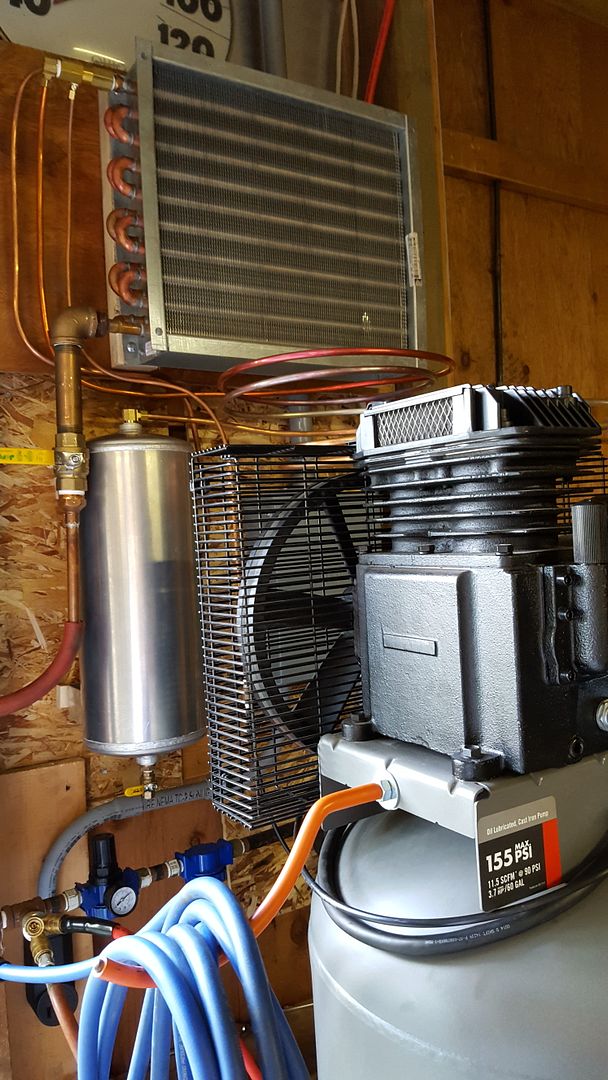
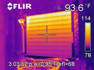
Here is a thermal image showing how this works. There is about 30+ feet of tube length in the condenser alone.
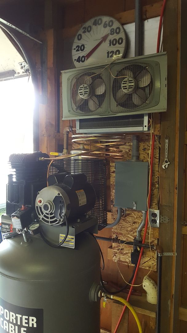
May add a small fan to suck air thru the condenser to better cool the rear tube riser.
Well I added a fan yesterday to help cool the upper condenser tubes just in case. The fan pulls air thru from the rear.
I may use a solid state relay 220vac input with a 120vac output control $18.00 to run from the compressor switch if I want to get fancy later.
https://www.automationdirect.com/static ... relays.pdf
AD-SSR610-AC-280A Solid state relay, panel mount, hockey puck style, 90-280 VAC input voltage, SPST, normally open SCR, 10A contact rating, 24-280 VAC load voltage, zero cross.
The compressor head purge valve is located up at the top of the condenser input. It purges only the 7 foot 3/8" copper line to the pump head. The compressed air from the head runs thru about 7 feet of coiled 3/8" copper coiled in a service loop to help cool and protect from compressor vibration. The compressed air enters the frontside snake of the condenser. It then runs downward to a water trap down drain then runs back up the backside snake. It then runs down to the backside middle of the aluminum tank for more cooling and water separation. The tank entry 90 degree elbow helps sling any water from the air. There is also a water drain valve at the bottom of the small tank. The air runs thru the top of the small tank thru another service loop coil and to the old one-way purge valve in the main tank. The system delivers dry air during the few minutes it runs to recover. We have a total of five water drains throughout the entire system. There is about a 125 degree difference in air temperature at the compressor head exit to the main tank entry. Very happy with the results so far.
Here is a thermal image showing how this works. There is about 30+ feet of tube length in the condenser alone.
May add a small fan to suck air thru the condenser to better cool the rear tube riser.
Well I added a fan yesterday to help cool the upper condenser tubes just in case. The fan pulls air thru from the rear.
I may use a solid state relay 220vac input with a 120vac output control $18.00 to run from the compressor switch if I want to get fancy later.
https://www.automationdirect.com/static ... relays.pdf
AD-SSR610-AC-280A Solid state relay, panel mount, hockey puck style, 90-280 VAC input voltage, SPST, normally open SCR, 10A contact rating, 24-280 VAC load voltage, zero cross.
Last edited by Bigdogbro1 on Wed Aug 31, 2016 12:46 pm, edited 11 times in total.
-
hsolve
- 2 Star Member
- Posts: 95
- Joined: Tue Sep 22, 2015 4:23 am
Re: COMPRESSOR-CONDENSER TUBING PLUMBING
Good morning bigdogbro1.
A cooling fan switched through the compressor run circuit would do the trick. This would greatly improve the heat transfer and this condensation of the water vapor. Another thing these things the condensers are rated at much higher pressure that normal compressed air. I am supprised that more people arn't using them for air cooling and drying!
A cooling fan switched through the compressor run circuit would do the trick. This would greatly improve the heat transfer and this condensation of the water vapor. Another thing these things the condensers are rated at much higher pressure that normal compressed air. I am supprised that more people arn't using them for air cooling and drying!
-
Bigdogbro1
- 2.5 Star Member
- Posts: 101
- Joined: Tue Aug 18, 2015 9:20 am
Re: COMPRESSOR-CONDENSER TUBING PLUMBING
Thanks hsolve,
I found a SSR yesterday that would work fine if I decide to go that route. This condenser was new and a freebie. I wanted a single top to bottom 3/8" serpentine tube but then this one came along. It still works great even without the fan but the fan has been sitting around in the building for 25 years and it only took two S-hooks to hang in on the condenser coil. The fan pulls the air thru from the back help cooling the final rear output run from the hot front input run. I had to reconfigure this condenser to work from a split parallel dual run configuration to get a longer total run length. I like that it's compact and works well.
I found a SSR yesterday that would work fine if I decide to go that route. This condenser was new and a freebie. I wanted a single top to bottom 3/8" serpentine tube but then this one came along. It still works great even without the fan but the fan has been sitting around in the building for 25 years and it only took two S-hooks to hang in on the condenser coil. The fan pulls the air thru from the back help cooling the final rear output run from the hot front input run. I had to reconfigure this condenser to work from a split parallel dual run configuration to get a longer total run length. I like that it's compact and works well.