Everlast CNC Port Errata - How it really works

Discussion forum for RazorWeld, Everlast, and all other plasma cutters.
Post Reply
Rodw
4 Star Member
4 Star Member
Posts: 780
Joined: Sun Aug 21, 2016 1:49 am
Location: Brisbane, Australia
Contact:

Everlast CNC Port Errata - How it really works

Post by Rodw »

Guys, I spent last weekend working out what was wrong with the Everlast CNC port in my PowerPlasma 50 purchased July 2016 from Everlast Australia. The documentation is riddled with errors so if you have one of these machines and are trying to get it going on a plasma table, ignore everything except this information. The documentation is identical on a number of other machines, so there is a good chance this applies to other Everlast machines.

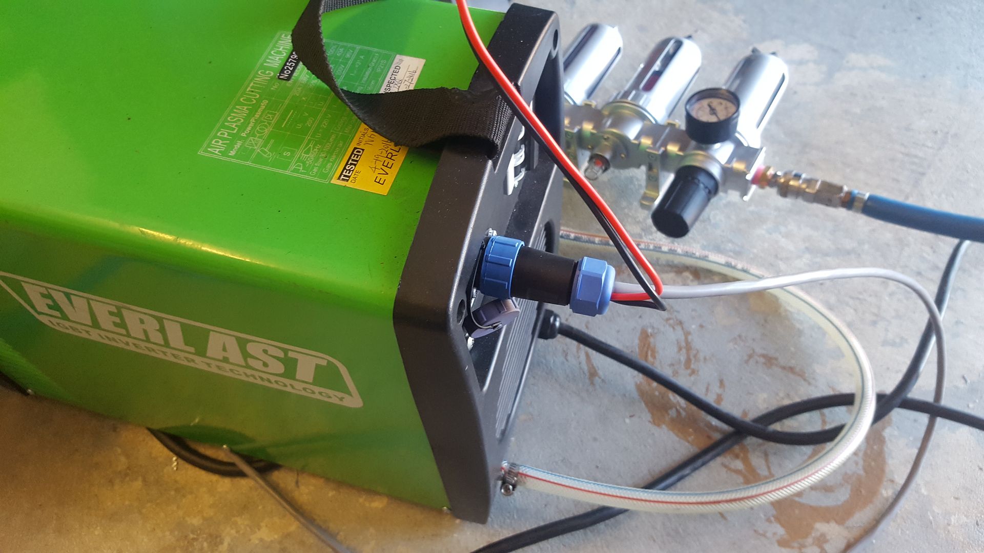
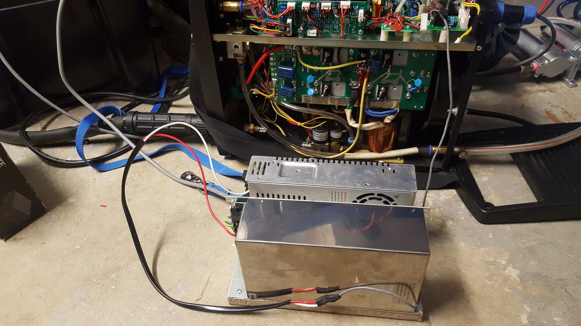
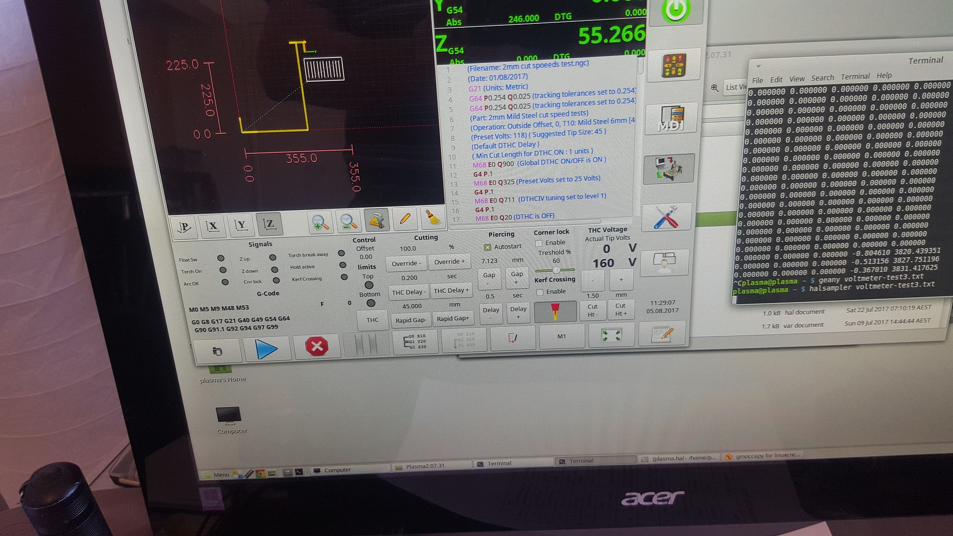
This is the board I am talking about (shown with connectors removed):

Image

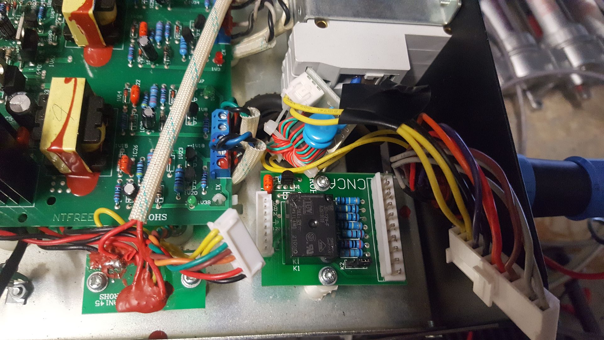
The 12 port CNC port is directly behind this board and you can see my connector (Weipu SP21 12 pin) is plugged in.

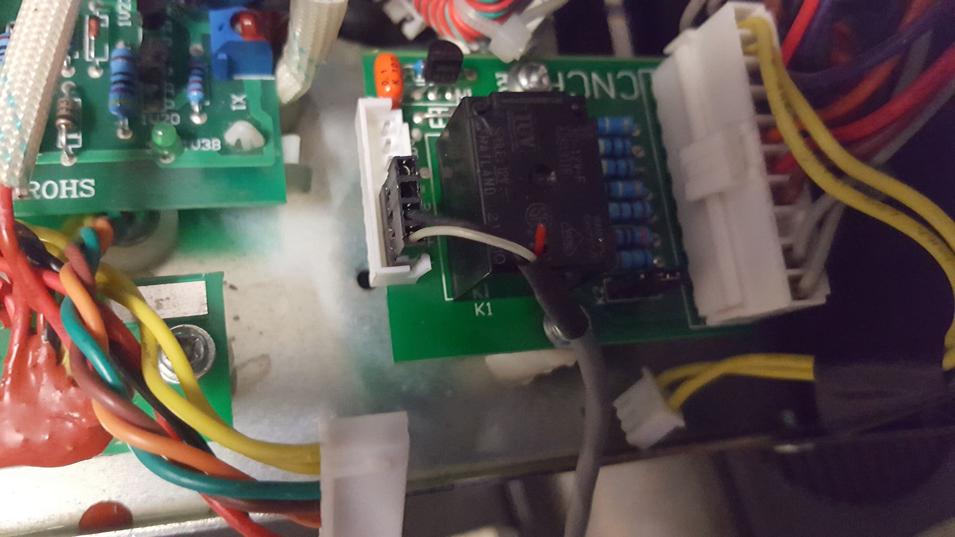
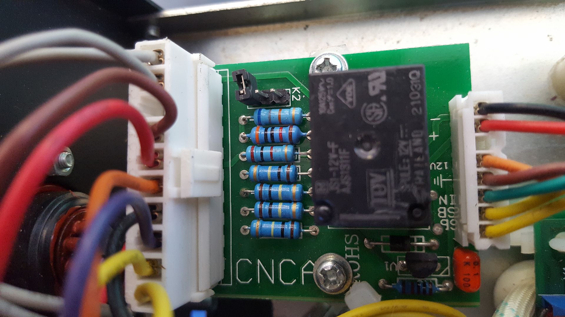
So here is another shot and notice the position of the link in the photo
Image

Error #1
The drawing in the manual is from the bottom side of the board (that is OK and easy to work out)
Error #2
The manual says that the 2 pins on the left select the divider ratio depending if they are shorted or not. This is incorrect. These 2 pins are connected on the board so shorting them has no effect. The correct position for the link is to connect it to the leftmost 2 pins or the rightmost 2 pins. More on this later.
Error #3
The manual states it is connected to the workpiece clamp via a 100k resistor. It is not connected to anything.
Error #4
The manual states that the pin numbers on the board are identical to the pin numbers on the connector. This is incorrect but the connector pinout is correct. The board signals has the divided voltage and the raw voltage swapped around. This is not a problem because you should not need to worry about the signals on the board.
Error # 5 - and this is a big one
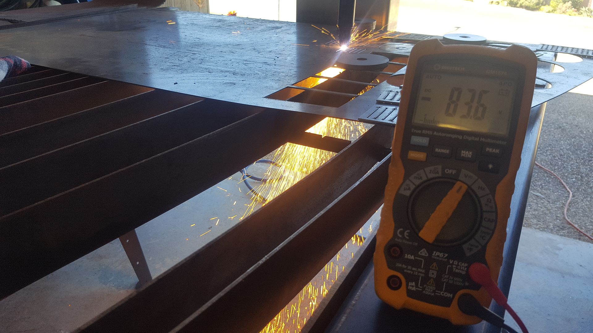
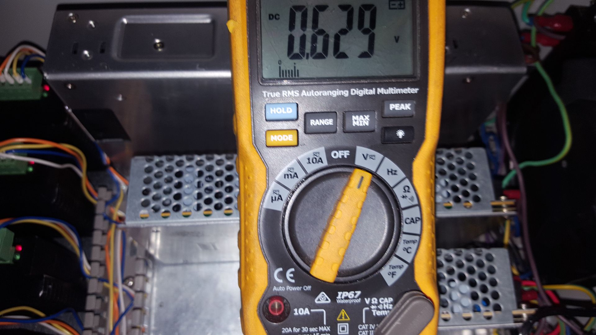
The 50:1 and 16:1 voltage dividers are incorrect! They are actually out by a factor of 1.5
The correct divider values are:
50:1 divider is actually 75:1 (I measured 76.145:1)
16:1 divider is actually 24:1 (I measured 24.529:1)

What does this mean?
If you want 75:1 division, place the link on the 2 pins closest to the CNC port connector
if you want 24:1 division, place the link on the 2 pins furthest from the CNC port connector.
Use the pinouts for the CNC port with confidence.

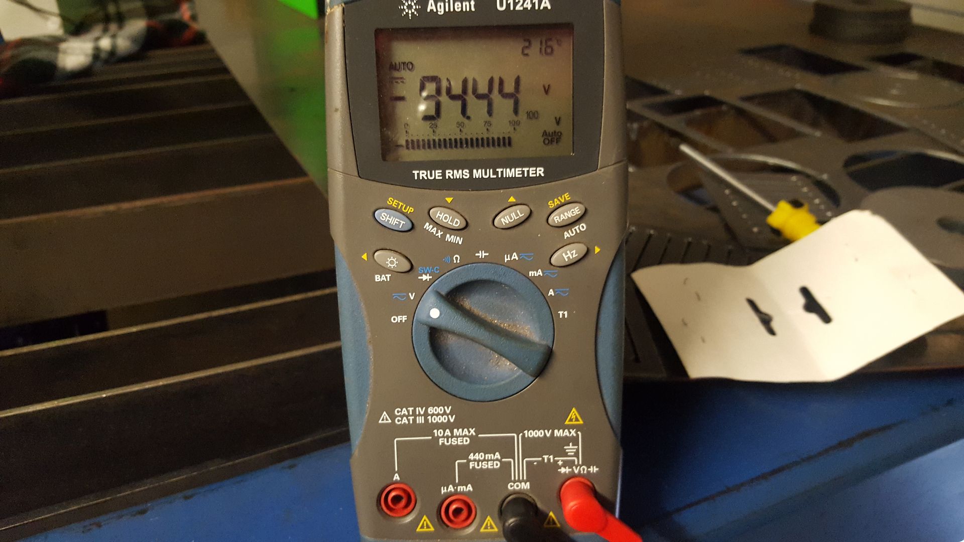
EDIT: Errata on the errata

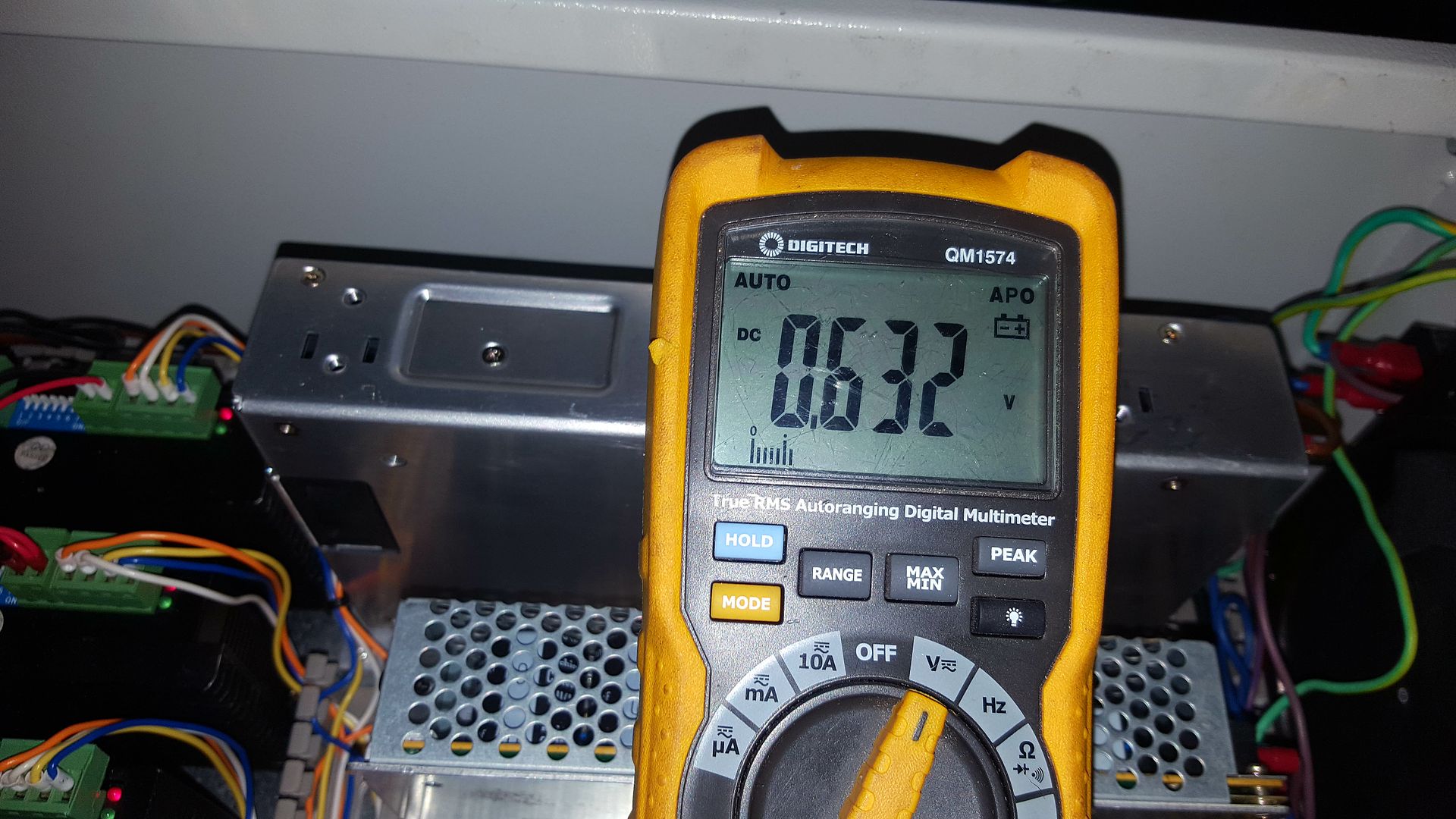
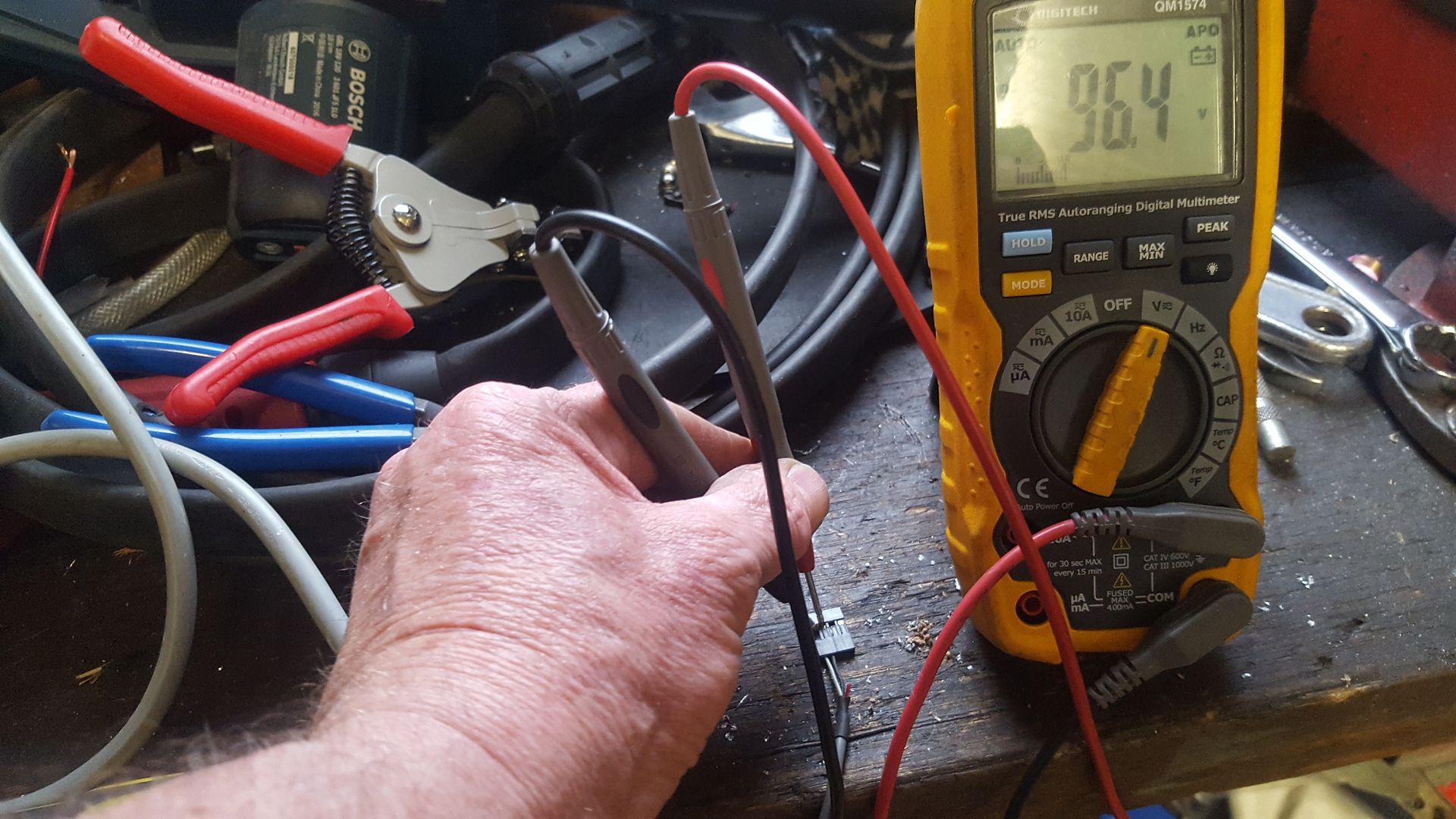
Further testing has revealed that the board actually is 16:1 when tested with a multimeter. The hardware I'm using to measure the divided voltage has a a 10 v range internally that can be scaled with an external resistor. The resistors on the Everlast divider are being counted as being part of the external scaling resistance so on my hardware Mesa (THCAD-10), the division varies with the scale set by an external resistor. eg
20 volt full scale reading becomes 24:1
10 volt full scale reading becomes 32:1

My next post will outline the tests I did to support these conclusions.
Last edited by Rodw on Thu Nov 08, 2018 4:08 pm, edited 3 times in total.
Rodw
4 Star Member
4 Star Member
Posts: 780
Joined: Sun Aug 21, 2016 1:49 am
Location: Brisbane, Australia
Contact:

Re: Everlast CNC Port Errata - How it really works

Post by Rodw »

For the last 12 months I've been building a plasma machine and table using LinuxCNC and a Mesa 7i76e plasma controller. When I fired up the machine for the very first cut, the torch voltage came in around 19-20 volts. This was clearly incorrect. I first thought that there was a bug in a component I had written in C for LinuxCNC. But that checked out 100% perfect after I wasted a few days troubleshooting. So I decided to check it out more closely once I had the machine dialled in on one material and a bit of time.

So the first thing I did was pull the machine apart and change the divider link position. This had no effect! I pulled the board out of the machine and inspected it in bright sunlight and I found the link problem.

But changing the link did not deliver meaningful results.
So I found a set of multimeter leads so I clipped off the probes and soldered them into the CNC port connector
Image
And ran them up to my multimeter and tried some cuts
Image
But the divided voltage still made no sense
Image
So I called in a mate who knows more about electronics and me and asked him to help me draw out the divider circuit. We worked out the link was shorting out a 67k resistor thus taking it out of the dividing circuit. I still did not have a clue about how things were working so I decided to waste the following morning drawing up the circuit myself. This let me uncover some of the other errors but I still could not work out what the divider ratio was.

So after talking to a couple of people and taking on board Tom Caudle's feedback on this forum, I remembered I had a couple of 48 volt power supplies laying around. So I connected them in series to get 96 volts.
Image
And I plugged them into the CNC board.
Image

Image
And read the divided voltage
Image

I'd also been lent another multimeter so I plugged it into the soldered in leads and noted about 2 volts loss across the resistors on the raw arc voltage (1.95 volts actually)
Image
While this was going on I could also see the voltage in LinuxCNC and I got it to log torch voltage and a few other stats at 1000 times a second.
Image

Initially, I was getting 150:1 and 75:1 dividers from this measurement process but then I remembered that I had already scaled the voltage as pte the Mesa THCAD manual which I was using for voltage measurement to double the full scale range. Once I measured the voltages before this scaling resistor and adjusting the calibration in LinuxCNC accordingly, I was getting perfect results.

So doing another cut after all of this using the same settings I used in the earlier photo with the sparks, I observed a constant voltage of 84-85 volts which is pretty well spot on with the voltage shown in the photo of the grey multimeter.
Last edited by Rodw on Wed Aug 09, 2017 11:11 pm, edited 1 time in total.
User avatar
acourtjester
6 Star Elite Contributing Member
Posts: 7754
Joined: Sat Jun 02, 2012 6:04 pm
Location: Pensacola, Fla

Re: Everlast CNC Port Errata - How it really works

Post by acourtjester »

Thanks for the report, I'm sure it will help others going on the same path :)
DIY 4X4 Plasma/Router Table
Hypertherm PM65 Machine Torch
Drag Knife and Scribe
Miller Mig welder
13" metal lathe
Small Mill
Everlast PowerTig 255 EXT
User avatar
rrossetti
1.5 Star Member
1.5 Star Member
Posts: 26
Joined: Thu Apr 17, 2014 4:34 pm
Location: uk
Contact:

Re: Everlast CNC Port Errata - How it really works

Post by rrossetti »

Hi
here is the fix for the 50-1 divider board to work correctly

as used by us at R-tech

You currently do not have access to download this file.
To gain download access for DXF, SVG & other files Click Here

Rodw
4 Star Member
4 Star Member
Posts: 780
Joined: Sun Aug 21, 2016 1:49 am
Location: Brisbane, Australia
Contact:

Re: Everlast CNC Port Errata - How it really works

Post by Rodw »

rrossetti wrote:Hi
here is the fix for the 50-1 divider board to work correctly

as used by us at R-tech
Awesome. Does that also give 16:1 with the link in the other position?
User avatar
rrossetti
1.5 Star Member
1.5 Star Member
Posts: 26
Joined: Thu Apr 17, 2014 4:34 pm
Location: uk
Contact:

Re: Everlast CNC Port Errata - How it really works

Post by rrossetti »

hi never tested 16-1
not needed on our setup
http://www.r-techwelding.co.uk/r-tech-c ... 4ft-x-4ft/
cheers rob
Rodw
4 Star Member
4 Star Member
Posts: 780
Joined: Sun Aug 21, 2016 1:49 am
Location: Brisbane, Australia
Contact:

Re: Everlast CNC Port Errata - How it really works

Post by Rodw »

rrossetti wrote:hi never tested 16-1
not needed on our setup
http://www.r-techwelding.co.uk/r-tech-c ... 4ft-x-4ft/
cheers rob
Rob, Thanks, I just have to change one resistor and I can scale to anything. Can you give me an idea of what the maximum torch voltage you've seen on the Everlast 50 amp? Nice table by the way.
Njcnc
1/2 Star Member
1/2 Star Member
Posts: 8
Joined: Tue Aug 29, 2017 11:04 am

Re: Everlast CNC Port Errata - How it really works

Post by Njcnc »

Oh man, thank you both so much for this info. I have been running Everlast plasma on two separate builds now with raw arc voltage and Proma THCs. I hated having to run raw arc voltage out of the until to the Proma. I'm heading home today after work to jumper that board and see if the Proma will read the 50:1 after the mod.
Njcnc
1/2 Star Member
1/2 Star Member
Posts: 8
Joined: Tue Aug 29, 2017 11:04 am

Re: Everlast CNC Port Errata - How it really works

Post by Njcnc »

Wanted to post back that I went ahead and did the mod pictured above. I have a powerplasma 60s and the board looked a tad different but found the same thing. Pin 4 at the plug is a black wire going to pin 7 on the board. Pin 6 at the plug is a red wire going to pin 5 on the board. Jumped the resistor at pin 7 on the board and fed it into the Proma's 50:1 divider. I got a bit over 90 volts firing in the air and about 62 cutting. The Proma will read as low as 45v so this is going to work out, no more running raw arc voltage out of the case. Here was a cut done in 1/8" plate at 75ipm, @45amps and the THC set at 62v. Had almost no dross, just a quick tap with a hammer took it off.
IMG_20170902_133816.jpg

You currently do not have access to download this file.
To gain download access for DXF, SVG & other files Click Here

Rodw
4 Star Member
4 Star Member
Posts: 780
Joined: Sun Aug 21, 2016 1:49 am
Location: Brisbane, Australia
Contact:

Re: Everlast CNC Port Errata - How it really works

Post by Rodw »

Hmm,

Further testing has revealed that the Everlast manual is correct about the division ratios. They are indead 16:1 and 50:1
BUT:
Many THC's must have some sort of scaling resistance internally to scale the input voltage to suit their internal ADC. They may see the Everlast division resistors as an extension of their divider network and display erroneous results.

So shorting out a resistor as shown may work on one THC but be incorrect on another.
In my case, my THC hasa 0-10 volt sensing range internally and can be configured using an external resistor to whatever you like;

So with the divided voltage disconnected from my voltage sensing hardware, a multimeter shows the dividers are indeed 16:1 and 50:1 but as soon as plug the wires into my sensing hardware, the voltage division at the same point becomes:

Code: Select all

Native 0-10V range   Dividers of 32:1 and 100:1
Extended 0-20V range Dividers of 24:1 and 75:1
 
So it seems you need to test against a known voltage to confirm the final dividers on your hardware. Just also be aware that an unloaded DC switch mode power supply may still have a significant AC ripple in it.
custommetal2001
1/2 Star Member
1/2 Star Member
Posts: 2
Joined: Sat Jan 20, 2018 2:52 pm

Re: Everlast CNC Port Errata - How it really works

Post by custommetal2001 »

NJCNC
How exactly did you hook up you THC on the everlast. I have tried thru the CNC port but cannot get it to work. your help will be appreciated.
Rodw
4 Star Member
4 Star Member
Posts: 780
Joined: Sun Aug 21, 2016 1:49 am
Location: Brisbane, Australia
Contact:

Re: Everlast CNC Port Errata - How it really works

Post by Rodw »

custommetal2001 wrote:NJCNC
How exactly did you hook up you THC on the everlast. I have tried thru the CNC port but cannot get it to work. your help will be appreciated.
I used the CNC port
The pinout for the circular connector in the manual is correct.
The voltage divider is 16:1 or 50:1 depending on if the link is connected or not
The volts read by your THC may count the Everlast resistor divider network as being part of its own circuit and alter the divided volts read (mine did). This can alter the divider ratio.
You need to make sure your circuit draws enough current to make the ArcOK relay in the plasma cutter to operate reliably. If you don't, the contacts will oxidise and not work. You might need a pull up or pull down resistor so the current is enough to plough through the oxidisation. (1k 1 W resistor on a 24 volt system works) This is not an Everlast fault but is just a feature of how relays work...

Other than that, you just follow your nose. To say it does not work is not informative so we can't really help you. There are many things that make things not work with a plasma cutter from your wiring, not asserting the spindle at speed signal through to the Gcode.
jawneelogik
1 Star Member
1 Star Member
Posts: 13
Joined: Tue Apr 03, 2018 11:52 am

Re: Everlast CNC Port Errata - How it really works

Post by jawneelogik »

Hello out there, I'm really hoping someone is still monitoring this thread. I've got big problems with cut quality and I own an Everlast Powerplasma 60S.

Let me first state up front that in the world of plasma cutting, I am a total noob, but I know enough about motion control to be dangerous. I bought this table from "a guy" who had it squirreled away in the back of his hot rod shop collecting dust. It wasn't even moving properly let alone cutting so I foolishly said I would be interested in buying it "as is."

My setup is as follows: 4'x8' table with newly constructed water pan, Mach3, G540, Proma THC-150, floating head torch mount (this was something I had to construct, but now works well,) Everlast Powerplasma 60S c/w PTM-60 machine torch.

The Everlast cutter is not necessarily what I would have chosen, but it was almost unused and came with the table. It comes with very little in the way of suggested parameter settings info per material (air pressure settings, current settings cutting speed, etc.). I've also found that I have to set my THC voltage setting to about half what I've seen others using (60V) in order to keep the nozzle anywhere near the 0.06" cutting height under TH control. One good thing about this unit and torch is it uses "Back striking ignition" instead of HF, so there is less EMF noise.

Up to now, I have been utilizing a ToM macro that I got from Adrian H. (thx. buddy) over at tamerisktechnicals.com It works just fine., but I'm thinking of trying one of the THC enabled posts (MP-1000) when I get time. The Proma unit is wired into the back of the 60S and uses raw voltage for sensing arc length. I've run the THC-150 in test mode and Mach seems to be reading and responding to the up/dn, Arc-OK signals as expected, so all my inputs to mach appear to be correct.

My problem is the wildly inconsistent results I continue to get. Even when cutting straight lines on relatively flat material, I can observe the torch constantly moving up and down and sometimes even losing penetration. I've tried changing various parameters to stabilize it, but can't get it where I feel it should be speed and/or quality wise; certainly not compared to what I've seen others produce.
So, after all that my question(s) are, can someone please explain in detail what the following parameters actually do (what is their effect?), and what would be a reasonable setting for each? And, if you don't mind sharing, could you tell me what sort of performance I should expect from this cutter?

THC-150:
volts = ? (as I stated above, I am operating in the 60v range, but most numbers I have seen from others say 100 to 120V)
HYS = ?
D-T = ?

Mach3:
THC Max = ?
THC Min = ?
Z Speed = ?
Antidive = ? (what is this function? I have pushed the button and the LED comes on, but I haven't detected any change in behavior.)

THC On/Off = ? (I have this button on my screen, but it seems to be disabled. Nothing happens when it is clicked. There is also a reset button next to it that also does nothing.)

Torch On = ? (This appears to work as expected. If the cutter is powered on, I can press this button and the torch will ignite. I don't use this very often so as to save tips, etc.)

I know this is a long winded post, but I wanted to included as much info as I could. I managed to score a small contract to cut plate material for a small structural steel fabricator in my neighborhood, but if I can't get this thing working consistently/reliably, I'm finished. Please, anyone. Help.

Thx. John
Rodw
4 Star Member
4 Star Member
Posts: 780
Joined: Sun Aug 21, 2016 1:49 am
Location: Brisbane, Australia
Contact:

Re: Everlast CNC Port Errata - How it really works

Post by Rodw »

I feel your pain. There are so many issues that could be causing your problems.

First off, the Everlast should have come with a flow measuring device with a ball bearing in it to set air flow/pressure. Something like this.
http://onlineweld.com/flowmeter-cv0087- ... fimet.html

If you are not properly earthed you can experience RFI noise in the torch voltage. I experienced this and I reworked all earthing and added an RFI filter to my control box power supply and also added a filter to the high voltage input before the divider board. Everlast suggested adding a bypass capacitor here but we added more filtering.

You really need an oscilloscope to see if the signal is noisy. One is built into LinuxCNC which was very helpful but in the end I bought one so I could see the noise first hand.

I would not be too concerned about the lower voltage. It could be just a calibration issue in the voltage sensing circuit. Comparing notes with Rtech who posted earlier on this thread, they said the larger torch (which I think you have) ran consistently about 10 volts lower than the smaller torch on the 50 amp machine. IN my experience the Everlast runs consistently lower than the Hypertherms.

Of course your erratic torch height control could just be a calibration issue with your THC. I can't help you there.
jawneelogik
1 Star Member
1 Star Member
Posts: 13
Joined: Tue Apr 03, 2018 11:52 am

Re: Everlast CNC Port Errata - How it really works

Post by jawneelogik »

rodw, Thanks so much for your reply. This thing has literally been eating my lunch!

The flow measuring device you linked to was not included in any of the bits I received, but that is not surprising since I bought the whole jumble on an as-is, "get this P.O.S. outta my shop now!" basis.

Looking at the picture on the website, it appears that the trick is to set the air inlet pressure so as to maintain flow rate based on the position of the little ball, and that this is something that is to be adjusted whenever a nozzle size is changed. Have I got that right? I.e The machine is designed to operate with a constant flow rate regardless of nozzle size; one simply adjusts the inlet pressure to compensate for changes in nozzle size while maintaining fixed airflow rate? (That was a mouthful!)

Currently I have my air inlet pressure set to the max that the manual says is allowed (Amazing, it actually has a manual. It's about as useful as a Harbor Freight manual, but it has one, none-the-less!) Whenever I have tried to set a lower pressure, for-example, when using a smaller nozzle, I get erratic results (failure to pierce or loss of arc prior to pierce or sometimes even while traveling)

From your comments, I'm suspecting that you are using LinuCNC for control so my questions re. the various mach THC parameters, their functions and suggested setpoints will probably not ring any bells. I am seriously considering moving this thing over to Linux, but right now I don't think my biggest problems are related to motion control. My XYZ is good for the most part.

Again, I thank you for your reply and any further info you can pass on.

John
User avatar
rrossetti
1.5 Star Member
1.5 Star Member
Posts: 26
Joined: Thu Apr 17, 2014 4:34 pm
Location: uk
Contact:

Re: Everlast CNC Port Errata - How it really works

Post by rrossetti »

hi guys
the reason you are getting poor cutting with these machines is the torch the ptm60 it is now a old design blow back torch
you need a better torch look at the pm70 by tecmo (http://www.tecmo.it/upld/repository/File/03.PH.pdf)this will fit and use the same consumables as a powermax 45
we use these now on all our machines

https://www.r-techwelding.co.uk/r-tech- ... ng-system/
Heavychevy
1 Star Member
1 Star Member
Posts: 11
Joined: Mon Jul 23, 2018 10:21 pm

Re: Everlast CNC Port Errata - How it really works

Post by Heavychevy »

I would like to say thank you for posting this fix. I have a everlast power plasma 80s and this works perfect for the proma thc! My board was different than the one above but the pinout was the same.

You currently do not have access to download this file.
To gain download access for DXF, SVG & other files Click Here

Diy 5x10 plasma table
Everlast 80s plasma Everlast 250 tig
Lincoln 350mp mig
Bridgeport series 1 and 2
Webb 3vh vertical mill
Brown and sharpe horizontal mill
South bend 14.5 x60 metal lathe
Old 65 ton piranha iron worker
Heavychevy
1 Star Member
1 Star Member
Posts: 11
Joined: Mon Jul 23, 2018 10:21 pm

Re: Everlast CNC Port Errata - How it really works

Post by Heavychevy »

Well it works!! My voltage test show 68-70 volts at .060 cut height on .250 plate 60 amp. Book specs for the everlast are 128 volts. Dont know if I believe book specs from everlast or trust the proma voltage reading? Does anyone else have a voltage spec they use or have found for the everlast on .250 plate?

https://youtu.be/EIkTG06d-0E
Diy 5x10 plasma table
Everlast 80s plasma Everlast 250 tig
Lincoln 350mp mig
Bridgeport series 1 and 2
Webb 3vh vertical mill
Brown and sharpe horizontal mill
South bend 14.5 x60 metal lathe
Old 65 ton piranha iron worker
Buckmaster1967
2 Star Member
2 Star Member
Posts: 73
Joined: Wed Oct 05, 2016 8:52 am

Re: Everlast CNC Port Errata - How it really works

Post by Buckmaster1967 »

Rodw wrote: Sun Feb 11, 2018 5:17 am
custommetal2001 wrote:NJCNC
How exactly did you hook up you THC on the everlast. I have tried thru the CNC port but cannot get it to work. your help will be appreciated.
I used the CNC port
The pinout for the circular connector in the manual is correct.
The voltage divider is 16:1 or 50:1 depending on if the link is connected or not
The volts read by your THC may count the Everlast resistor divider network as being part of its own circuit and alter the divided volts read (mine did). This can alter the divider ratio.
You need to make sure your circuit draws enough current to make the ArcOK relay in the plasma cutter to operate reliably. If you don't, the contacts will oxidise and not work. You might need a pull up or pull down resistor so the current is enough to plough through the oxidisation. (1k 1 W resistor on a 24 volt system works) This is not an Everlast fault but is just a feature of how relays work...

Other than that, you just follow your nose. To say it does not work is not informative so we can't really help you. There are many things that make things not work with a plasma cutter from your wiring, not asserting the spindle at speed signal through to the Gcode.
Hello,
I have the Everlast 60s. I think I followed the instructions correct, but can't get the plasma to strike an arc. I am using a Masso controller and the Proma THC-150. I did the Pin 4 at the plug is a black wire going to pin 7 on the board. Pin 6 at the plug is a red wire going to pin 5 on the board. Jumped the resistor at pin 7 like you said. I ran the number 4 pin on the plug to to the negative on the THC 150, and the number 6 pin on the plug to the plus on the bottom of the PTC 150. I don't think I am getting any voltage from these pins. The PTC 150 never reads anything but 3 flat lines. The OK relay works, air comes out the torch, but no firing of the arc. I know it is something simple, and without you seeing all my setup, it could be anything. You have any ideals?
Rodw
4 Star Member
4 Star Member
Posts: 780
Joined: Sun Aug 21, 2016 1:49 am
Location: Brisbane, Australia
Contact:

Re: Everlast CNC Port Errata - How it really works

Post by Rodw »

I can't really help you. I sold my Everlast a few months ago and now have a 120 amp Thermal Dynamics. My first thought is that if air comes out of the torch when the trigger is pressed, the torch trigger is firing but the arc isn't so it could be a machine problem. Check for error warnings on the plasma console and see if you can trigger the torch manually with M3/M5 or whatever gcode turns it on. Silly question, but is your earth clamp attached to the material?

Are you using a machine torch? I had to modify the internal wiring inside the machine torch so it would turn on.

Just be aware that I was not the one soldering links on the board. I used the machine as is as I could adjust my control software to suit the divider.

If it helps, Thermal Dynamics also had documentation errors as they had the polarity of both raw arcs and divided voltage reversed!
Buckmaster1967
2 Star Member
2 Star Member
Posts: 73
Joined: Wed Oct 05, 2016 8:52 am

Re: Everlast CNC Port Errata - How it really works

Post by Buckmaster1967 »

Thank you. Home and going back at it. I added a LTM-CNC Straight torch, going to reinstall my old torch and see if I can fire her up. Without a doubt, it is some simple I am missing. I built a 5'x11' cnc water table, 3 axis, auto water filling table. Got everything as far as axis working. Now to get this plasma working. I am alot like the guy who built the first car, and after it was built, it dawned on hime, he did'nt know how to drive. You like your Thermal Dynamics plasma better? If so, why? pros and con vs the Everlast.
Rodw
4 Star Member
4 Star Member
Posts: 780
Joined: Sun Aug 21, 2016 1:49 am
Location: Brisbane, Australia
Contact:

Re: Everlast CNC Port Errata - How it really works

Post by Rodw »

Buckmaster1967 wrote: Tue Jan 29, 2019 3:22 pm Thank you. Home and going back at it. I added a LTM-CNC Straight torch, going to reinstall my old torch and see if I can fire her up. Without a doubt, it is some simple I am missing. I built a 5'x11' cnc water table, 3 axis, auto water filling table. Got everything as far as axis working. Now to get this plasma working. I am alot like the guy who built the first car, and after it was built, it dawned on hime, he did'nt know how to drive. You like your Thermal Dynamics plasma better? If so, why? pros and con vs the Everlast.
I know the feeling about venturing into the unknown.

My reasons for the upgrade were outlined in a post on this thread
viewtopic.php?f=103&t=22826&start=50#p165972
It was going to be a 3 phase Hypertherm and then it became a HT 65 amp machine, then I found this machine brand new at a ridiculous price! It certainly got a much cleaner signal than the everlast but that might be a 3 phase thing. I have not had it long enough to really know if I did the right thing as I have not got my Linuxcnc THC fully tuned in yet but its very close (and the best results to date)
Buckmaster1967
2 Star Member
2 Star Member
Posts: 73
Joined: Wed Oct 05, 2016 8:52 am

Re: Everlast CNC Port Errata - How it really works

Post by Buckmaster1967 »

Well, found the problem. The straight torch I purchased for $162 is a HF torch. Everlast 60S 2015 and newer is a Blow Back torch $500. That is why it would not fire. Now, do I pay $500 for a torch, or purchase another plasma and sell the Everlast. Have not had any issues with the Everlast, except hard to find consumables.
Plasmamonster
1/2 Star Member
1/2 Star Member
Posts: 7
Joined: Mon Mar 09, 2020 9:16 pm

Re: Everlast CNC Port Errata - How it really works

Post by Plasmamonster »

This is interesting. I thought I was the only one with these issues with the 80s. It seems not to go from pilot arc to cutting arc. Maybe this is the issue : )
Plasmamonster
1/2 Star Member
1/2 Star Member
Posts: 7
Joined: Mon Mar 09, 2020 9:16 pm

Re: Everlast CNC Port Errata - How it really works

Post by Plasmamonster »

Buckmaster1967 wrote: Tue Jan 29, 2019 6:58 pm Well, found the problem. The straight torch I purchased for $162 is a HF torch. Everlast 60S 2015 and newer is a Blow Back torch $500. That is why it would not fire. Now, do I pay $500 for a torch, or purchase another plasma and sell the Everlast. Have not had any issues with the Everlast, except hard to find consumables.
No, just get one from Aliexpress. Around $100.
Build it yourself.
Post Reply

Return to “RazorWeld, Everlast, & All Other Plasma Cutters”